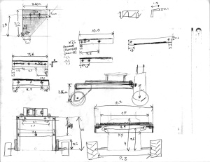
This project is both a robotics project and an experiment comparing the effectiveness of several different control theory algorithms. My idea is a robot that will balance on a cylinder that is turned on its side as illustrated in the diagram on right.
So far I’ve made the physical structure of the cart, and a circuit board containing the motor controller and sensors.
The project uses both an accelerometer and a gyro for orientation data and a wheel encoder to get accurate velocity data. Eventually, it will be possible to control the robot remotely by adjusting the target velocity.
I hope to investigate several different controllers including at least PID and Fuzzy Logic. If possible, I will also try to make these controllers self adaptive so that they can tune themselves.
Related Posts
Much more information about the individual components is available in these posts
- Wireless Modules with Arduino
- Photointerruptor Test Circuit
- Optical Quadrature Encoder Circuit
- Greater San Diego Science and Engineering Fair Awards
Display
Simulation
An applet that simulates this system is accessible here: http://keegan.webhop.net/applets/cynbot_sim
The yellow circle is the cart. Currently, the controller is not simulated so the position of the mouse relative to the center of the screen is the PWM value sent to the simulated motor. As you can see, it’s almost impossible to balance the cart on top of the cylinder manually even though the moment of inertia of the cylinder is set to a relatively high value. The cart falling off the cylinder isn’t simulated either so it’s as if the cart sticks to the surface of the cylinder.
Here are some pictures:


